Floor planning:
Floorplanning is the art of any physical design. A well and perfect floorplan leads to an ASIC design with higher performance and optimum area.
Floorplanning can be challenging in that, it deals with the placement of I/O pads and macros as well as power and ground structure.
Before we are going for the floor planning to make sure that inputs are used for floorplan is prepared properly.
Inputs for floorplan:
- Netlist (.v)
- Technology file (techlef)
- Timing Library files (.lib)
- Physical library (.lef)
- Synopsys design constraints (.sdc)
- Tlu+
 |
| fig 1. ASIC design |
After physical design database creation using imported netlist and corresponding library and technology file, steps are
- Decide core width and height for die size estimation.
- IO pad sites are created for placement of IO pad placement.
- Placement of macros.
- The standard cell rows created for standard cell placement.
- Power planning (pre routing)
- Adding physical only cells
apart from this aspect ratio of the core, utilization of core area, cell orientation, and core to IO clearance are also taken care of during the floorplan stages.
floorplan control parameter:
core area depends upon :
floorplan control parameter:
core area depends upon :
- Aspect ratio: Aspect ratio will decide the size and shape of the chip. It is the ratio between horizontal routing resources to vertical routing resources (or) ratio of height and width. Aspect ratio = width/height
- Core utilization:- Utilization will define the area occupied by the standard cells, macros, and other cells.If core utilization is 0.8 (80%) that means 80% of the core area is used for placing the standard cells, macros, and other cells, and the remaining 20% is used for routing purposes.
core utilization = (macros area + std cell area +pads area)/ total core area
Pad placement:
In ASIC design three types of IO Pads. Generally pad placement and pin placement is done by Top-Level people. It is critical to the functional operation of an ASIC design to ensure that the pads have adequate power and ground connections and are placed properly in order to eliminate electro-migration and current-switching related problems.
- Power
- Ground
- Signal
What is electromigration? We will discuss it later in depth.
Electro-migration is the movement or molecular transfer of electrons in the metal from one area to another area that is caused by a high density electric current inflows in the metal. High density current can create voids or hillocks, resulting in increased metal resistance or shorts between wires and it can degrade the ASIC performance.
One can determine the minimum number of ground pads required to satisfy the current limit, and the required number of power pads equal to the number of ground pads.
Where
Ngnd = Itotal/Imax
Ngnd = number of ground pads
Itotal = total current in design (sum of static and dynamic currents)
Imax= max EM current
Current switching noise is generated when there is a transition between states on metal layers. This will cover in crosstalk topic.
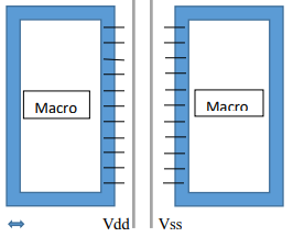
Macro placement:
Macros may be memories, analog blocks. Proper placement of macros has a great impact on the quality and performance of the ASIC design. Macro placement can be manual or automatic.
Manual macro placement is more efficient when there are few macros to be placed. Manual macro placement is done based on the connectivity information of macros to IO pin/pads and macro to macro. Automatic macro placement is more appropriate if the number of macros is large.
Types of macros:
- Hard macros: The circuit is fixed. We can’t see the functionality information about macros. Only we know the timing information.
- Soft macros: The circuit is not fixed and we can see the functionality and which type of gates are using inside it. Also we know the timing information.
Guidelines to place macros:
- Placement of macros are the based on the fly-lines ( its shows the connectivity b/w macro to macro and macro to pins) so we can minimize the interconnect length between IO pins and other cells.
- Place the macros around to the boundary of the core, leaving some space between macro to core edge so that during optimization this space will be used for buffer/inverter insertion and keeping large areas for placement of standard cells during the placement stage.
- Macros that are communicating with pins/ports of core place them near to core boundary.
- Place the macros of same hierarchy together.
- Keep the sufficient channel between macros
channel width = (number of pins * pitch )/ number of layers either horizontal or vertical
Eg. Let’s assume If there are two macros having 50 pins and the pitch values are 0.6 and the total number of horizontal and vertical layers are 12. Means M0 M2 M4 M6 M8 M10 are horizontal layers and M1 M3 M5 M7 M9 M11are vertical layers.
Channel width = ((50+50)*0.6)/6
= 10
- Avoids notches while placing macros, if anywhere notches is present then use hard blockages in that area.
- Avoid crisscross connection of macro placement.
- Keep keep-out margin around the four sides of macros so no standard cells will not sit near to Macro pins. This technique avoids the congestion.
- Keep placement blockages at the corners of macros.
- For pin side of macros keep larger separation and for non-pin side, we can abut the macros with their halo so that area will be saved and Halo of two macros can abut so that no standard cells are placed in between macros.
- Between two macros at least one pair of power straps (power and Ground) should be present.
 |
| fig: placement of IO pads, standard cells and macros hierarchy wise |
 |
| Fig. Abutted non-pin side macros with abutted halo |
 |
| fig: pin side macros with halo |
lots of iterations happen to get optimum floorplan. the designer takes care of the design parameter such as power, area, timing and performance during floorplanning.
types of floorplan techniques:
- Abutted:- When the chip is divided into blocks in the abutted design there is no gap between the blocks.
- Non abutted:- In this design there is a gap between blocks. The connection between the blocks is done through the routing nets.
- The mix of both: This design is a combination of abutted and non- abutted.
outputs of floorplan:
- get core and boundary area
- IO ports/pins placed
- macros placement done
- floorplan def file
key terms related to floorplan:
standard cell row:
- The area allotted for the standard cells on the core is divided into rows where standard cells are placed.
- The height of the row is equal to the height of the standard cell and width varies. The height varies according to multiple standard cell row height. there may be double-height cells, triple-height cells, etc.
- The standard cells will sit in the row with proper orientation.
 |
| fig: placement of standard cells in row |
fly lines:
- macros are placed manually using fly lines. fly lines are a virtual connection between macros and macros to IO pads.
- This helps the designer about the logical connection between macros and pads.
- Fly lines act as guidelines to the designer to reduce the interconnect length and routing resources.
- fly lines are of two types:
macros to IO pin:
 macros to macros fly lines:


halo(keep out margin):
- This is the region around the fixed macros so that no other macros and standard cell can be placed near to macros boundary
- the width of the keep out margin on each side of the fixed cell can be the same or different depending on how you define keepout margin.
- keeping the placement of cells out of such regions avoids congestion and produce better qor.
- Halo of two adjacent macros can be overlap.
- If the macros moved from one place to another place, the halo will also move.

ICC command for keepout margin:
create_keepout_margin -outer {10 10 10 10} macro_name -type soft/hard
create_keepout_margin -inner {10 10 10 10} macro_name -type soft/hard
Blockages :
- Blockages are the specific location where the placing of cells is blocked.
- Blockages will not guide the tool but it allows not to place the standard cells buffer and inverters at some particular area i.e by using blockages we blocked the area so no standard cells and other cells won't be placed.
- If the macros moved from one place to another place, blockages will not move.
- Blockages are of three types. a) soft b) hard c)partial
- only buffer can be placed.
- prevents from the placement of std cell and hard macro within the specified area during coarse placement but allows placement of buffer/inv during optimization, legalization and clock tree synthesis.
- create_placement_blockages -boundary {{10 20} {100 200}} -name PB1 -type soft
- No standard cells, macros and buffer/inv can be placed within the specified area during coarse placement, optimization, and legalization.
- Used to avoid routing congestion at macros corners.
- Control power rails generation at the macros.
- create_placement_blockages -boundry {{10 20} {100 200}} -name PB1 -type hard
- Partial blockages limit the cell density in the specified area.
- By default the blockage factor is 100% so no cells can be placed in that region but if we want to reduce density without blocking 100% area, we can change the blockage factor.
- create_placement_blockages -Boundry {10 20 100 200} -type partial -blocked_percentage 40 Partial blockages with a maximum allowed cell density of 60% (blocked % is 40) enclosed by a rectangle with corners (10 20) & (100 200)
- To allow unlimited usage of a partial blockage area specify a blockage percentage to zero.

No comments:
Post a Comment